
What is a PID controller?
 |
PID Controller |
A PID controller in the field of electrical engineering is a feedback control loop that calculates an error value as the difference between a desired setpoint (SV) and a measured process (PV) variable. It is used to minimise the error signal.
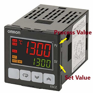 |
Error = PV - SV |

PID stands for Proportional, Integral, and Derivative, representing the three control actions involved in its operation. It is commonly used to control various systems, such as temperature, flow, and pressure, by continuously calculating an appropriate correction. The proportional term helps reduce the error, the integral term helps eliminate any offset, and the derivative term helps dampen the system's response to reduce oscillation. The combination of these three components provides a powerful and widely used control mechanism for electrical systems. It is a type of feedback controller system.

Applications of PID controllers in Electrical panel Systems
Temperature control: PID controllers are extensively used in heating, ventilation, and air conditioning systems for precise temperature regulation.
Speed control: They are employed in electric motors to manage and regulate rotational speeds (rpm) in applications such as industrial machinery, robotics, and automation.
Voltage regulation: PID controllers play a critical role in maintaining stable voltage levels in power supply systems, ensuring smooth and consistent electrical power delivery.
Process control: They are utilized in industrial processes, such as manufacturing and chemical plants, to maintain optimal operating conditions, improve efficiency, and enhance overall system performance.
Robotics: PID controllers help manage and stabilize the movements of robotic systems, ensuring precise and accurate positioning and control.
PID controller pinout and wiring diagram
The pin-out configuration of a PID controller can vary depending on the specific model and manufacturer. Typically, a PID controller includes multiple terminals for power supply connections, input signal connections, and output connections to the controlled device. These connections allow the PID controller to receive signals from sensors, process the input signals, and send control signals to actuators to maintain the desired system parameters. The exact pin-out configuration should be outlined in the user manual or datasheet provided by the manufacturer.
Installing a PID controller generally involves the following steps.
- Mounting: Fix the controller securely at an appropriate location, ensuring it is easily accessible for adjustments and maintenance according to the drawing.
- Wiring: Connect the power supply lines to the appropriate terminals of the controller. Attach the input signal wires from the sensors or transmitters to the input terminals, and connect the output wires to the output terminals leading to the controlled device or actuator.
- Configuration: Set the control parameters such as proportional band, integral time, and derivative time based on the specific system requirements. This step is crucial for the PID controller to function effectively and maintain the desired control parameters.
- Calibration: Adjust the setpoints and tuning parameters to achieve the desired response from the controlled device.
- Testing and Adjustment: Run the system and observe the performance. Make necessary adjustments to the controller settings if the system response does not meet the required specifications.
Always refer to the user manual provided by the manufacturer for detailed installation instructions specific to the model of the PID controller being used.
 |
PID Controller Connections |
Additional Links
https://falibert.blogspot.com/2021/06/how-pid-controller-works-control.html
https://web.facebook.com/watch/?ref=saved&v=228578129977601
https://goswitchgear.com/pid-controller-a-comprehensive-guide/
Thank you for the learning
UBApepi team.
UBApepi team.


![Do You Know About Surge Protection Device - [SPD] ⚔🌩](https://blogger.googleusercontent.com/img/b/R29vZ2xl/AVvXsEgRsyAlJa4e0fqNRlqntUDX35KZGmFX6nHHtHHvPFZ17ZnE7omwBZY8kXAbHcoEiPgT0ZR71wLM9tkPFXve4W-yPGp1XSVdfKymzaBD4yJ8oC0wIdiB1DSAnDZswM179gDcIFo2zOlCq5xV-cacxRECdjVVMCNihMpOk0T1TcyoA-s07wU5G1ELAOEB/w72-h72-p-k-no-nu/surge-protectors-for-ac-power-supply-system-t3-02.jpg)


0 Comments